1998 Hyundai Tiburon Engine Rewire
The Tiburon is my daily driver at the time of writing this (Oct 2017) and has been playing up for a while now. It would on occasion miss and more unusually around the same place which lead me to believe it was electrical noise. It would also bog down a real lot, checking with a diagnostic tool made me think it was a knock sensor issue since it was cutting timing. On the odd occasion it would cut out and fail to start for a few minutes. It did eventually come up with a crank position sensor error, I replaced it but this made me realise something had to be done, I was not convinced the sensor was faulty after only 80k km.
This car is intended as a project car but also my daily driver which means that I must step carefully, I must also be careful what I spend since there is still no guarantee that I can stay in Canada. The ultimate goal is to develop my own ECU system so that I can have some fun with more cars, the Tiburon will be the starting platform. So the objective of this project is to relocate the ECU to somewhere more accessible so that I can develop my own ECU in the near future.
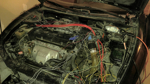
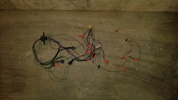
Admittedly this project took a lot longer than I expected, what didn't help was that many of the wires were different in colour than in the manual, I didn't take many pictures either as I never intended to write this up as a project. I first located the ECU which was underneath the drivers side dashboard, I was amazed by how many wires there were, I spent maybe a little too much time trying to decode what they were. I then proceeded to pull the wiring from the inside to the outside though the firewall, I split the wiring in half and labeled everything. To the left is the engine control wiring strewn around and the right is what I have left, this will go back through the firewall because all it controls are things not related to the engine such as the wiper, brake fluid, air CON, reverse switch and speed sensor.


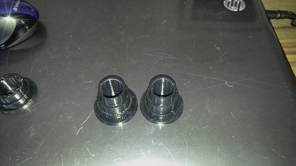
The dashboard was pulled so that I could get in to drill through the firewall. These two little plastic inserts which I printed from ABS would be used to protect the wires from which I drilled the holes.

There were a total of three holes drilled through the firewall, the far left for the injectors and CAM sensor, the middle for coils, crank, knock and the right solely for the sensors which could change such as the MAF and air intake temp sensor. An insert was placed on both sides, a plastic tube connecting the two was sealed in place.
The engine bay wiring was sorted and then sleeved and taped. I really hate making looms because if you want it to function as a daily driver and don't want the elements getting to it then you have to resort to a lot of tape. If it was a track car then I would just use the braided sleeve stuff, I did use a mixture of both but it was not quite as tidy as I would have liked. The right picture shows all of the engine control wiring passed through the tubes, excuse the mess.
Again I spent a little too much time trying to figure out what all of the extra wires were for from the ECU to the dashboard / main wiring loom. I total of about 20 more wires and I could only accurately figure out what five of them were for since the colours did not tally up with the manual. To the right shows the ECU bolted in place, the wiring hanging down is for the front oxygen sensor which will eventually connect to my wideband controller.
The next step was to fix the battery wiring to the main harness and to the starter motor. I used some jumper cable to feed the wires to the correct points, the issue I encountered originally was that the heavy gauge audio cable from the rear of the car was too fine to solder, I bodged something together and bound it in tape to stop shorts.
I bought some proper cable for the job to link the harness wiring to a point and also the starter motor cable to a point. I used crimped terminals but filled them with solder, if they wick properly then they are stronger than a crimp. The reason crimps are used is because with the right tools it's faster and harder to get wrong. To the right is the 00 gauge battery cable from the rear, I managed to find a large ring loop that I could insert the cable and fill with solder.
The battery cable was then bolted together with the main harness wire and the starter motor. For now I chose to bind it in tape again to stop shorts, I will 3D print a mount that will secure it properly in the near future. To the right is an example of the wiring for the injectors, I chose to use sleeve and heatshrink as this looks a lot better than tape.
Hello, if you have enjoyed reading this project, have taken an interest in another or want me to progress one further then please consider donating or even sponsoring a small amount every month, for more information on why you may like to help me out then follow the sponsor link to the left. Otherwise you can donate any amount with the link below, thank you!