Exploding Water Page 3
February 07/02/2016
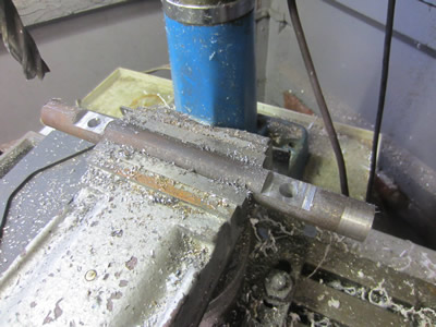
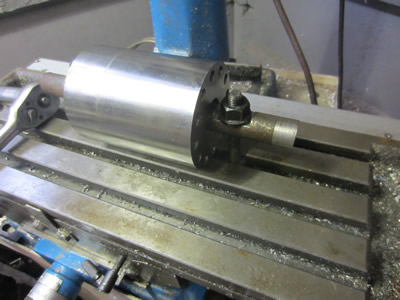
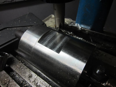
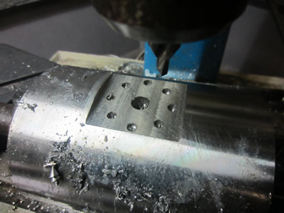
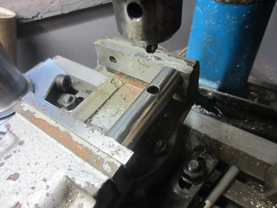
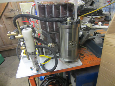
I finally got around milling the port in the vessel. First on the list was to work out how to bolt it down in the miller as it wouldn't fit in my vice and I had no special clamps. Instead I drilled a few holes in a bar and then milled a flat on them to give plenty of surface contact area, the bar was then placed through the vessel which allowed me to securely clamp it to the millers bed. I found out a carbide end mill and cut a slot for the port.
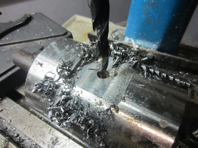
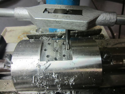
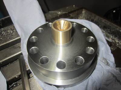
The port hole was drilled out to 10mm, then a series of eight holes were drilled and tapped to M6. I had to adhere to specific depths for the holes to ensure that the pressure rating was constant throughout to whole of the vessel, making sure there were no weak spots.
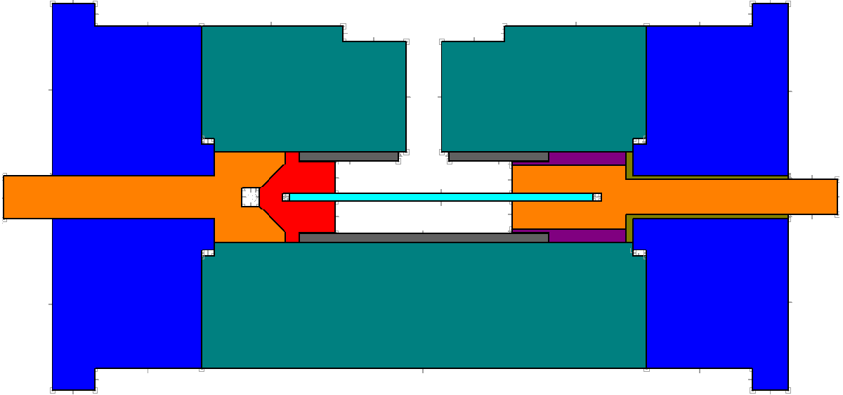
The picture below is a side view of the vessel, to scale. One of the end caps will be permanently fixed in place but the other will need to be removed to replace the wire electrode. The wire will be placed in a cartridge that is fixed to the right end cap, the part in red will separate from the left electrode when the cartridge is removed.
February 08/02/2016
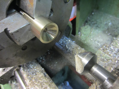
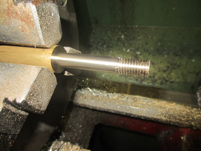
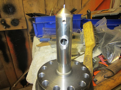
I first started with the left electrode made from a piece of 1 inch brass bar, I used a 45 rose to countersink one side.
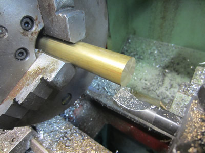
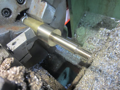
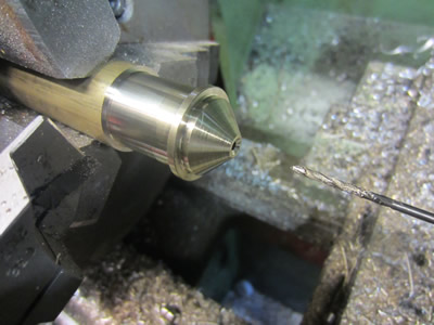
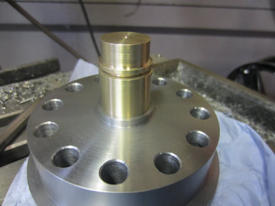
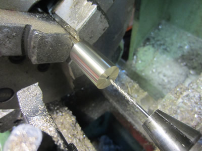
The electrode was made 0.01mm bigger than the hole it was going into, it took a great deal of effort to press it into the end cap. The next part was the male part of the electrode, it will have a grub screw placed in the side of it to secure the filament wire. When the parts are stacked together the design calls for the brass parts to measure 34mm in height, it was a little guess work with the male part and I figured I may have to alter other parts in order for it to assemble correctly but it turned out perfect, exactly 34mm.
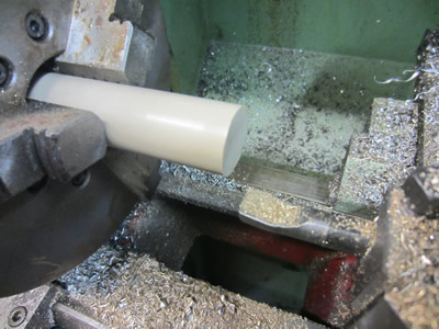
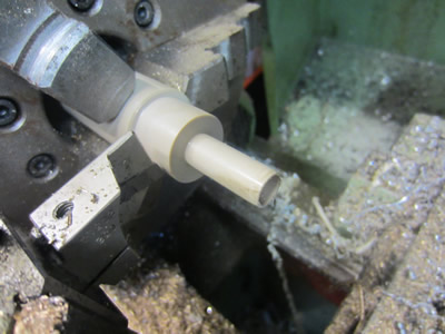
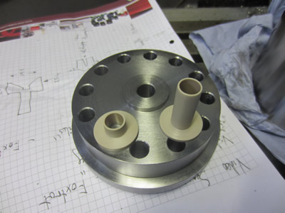
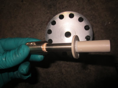
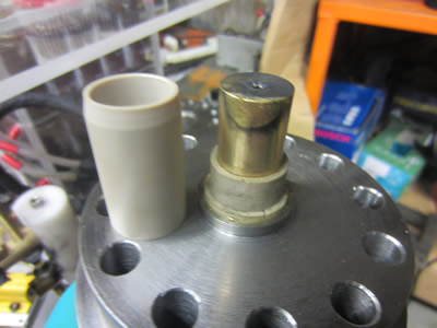
The peek insulators were wade for the other end cap.
February 15/02/2016
The right electrode was next on the list, it was also to be insulated from the vessel via a peek insulator. I used a thread sealant to ensure that there would be no chance of leaking, probably unnecessary due to the interference fit.
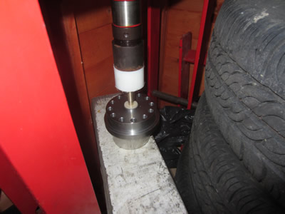
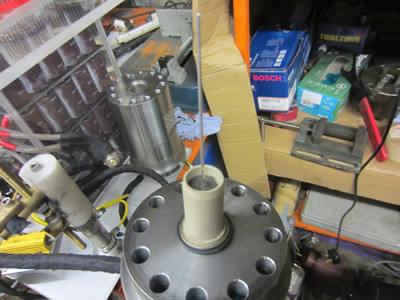
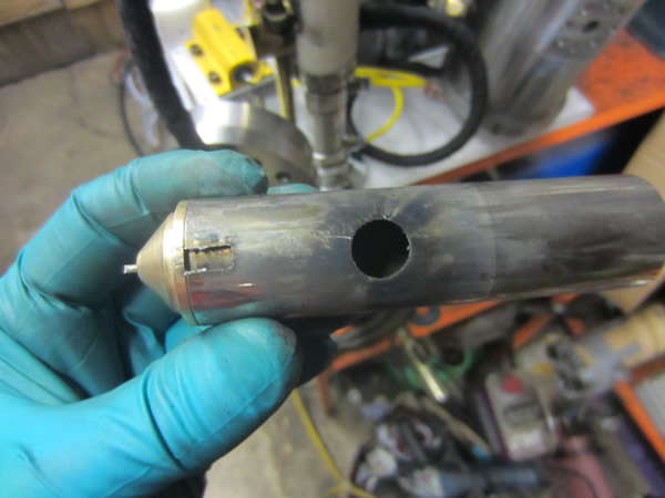
The fit was so tight that I had to use a hydraulic press, 4 tonnes. The first half pressed in perfect as the cap was flat against the wood, I had to use an aluminium ring spacer underneath it so that the electrode would not bed itself in the wood for the second half. Unfortunately I managed to bend the electrode as the spacer ring squashed unevenly into the wood so I had to modify the design of one of the peek spacers. I cut the tube to length, drilled a hole and cut a slot in it. A piece of aluminium wire was placed inside and the cap bolted to the vessel for a low power test.
The first fire was at 2kJ and it didn't manage to break the wire. The second test was 4kJ and it broke the wire but the plasma caused arcing between the right electrode and the stainless tube, it seems that modifying the insulator was a bad idea and I will have to sort this out. I did create a video but there is no point in posting it, my major problem is the amount of noise this thing produces, even through moulded ear plugs it's loud.
February 16/02/2016
A replacement peek spacer was made and another wire inserted into the vessel, I decided to wire the bank as 8kJ this time. The bank is simply too loud to be playing with and I certain don't want any trouble so this is why I chose to run it at it's maximum rating, for one last shot. The intention of the project was to also place water inside of the vessel to see what pressures it could attain but I simply could not continue with it.
The bank was charged to 7.4kJ at a voltage of 860Vdc. There are two bangs in the video, the first one being the switch and the wire exploding. The second bang is the aluminium vapour igniting, you can also see a flame in the vessel lasting for a second or two after the second bang. It is not quite clear how loud this was in the video but even with moulded ear plugs it was extremely loud, comparable to a hunting rifle.
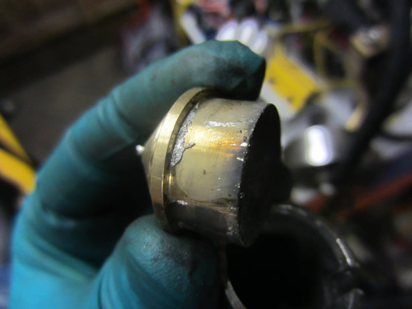
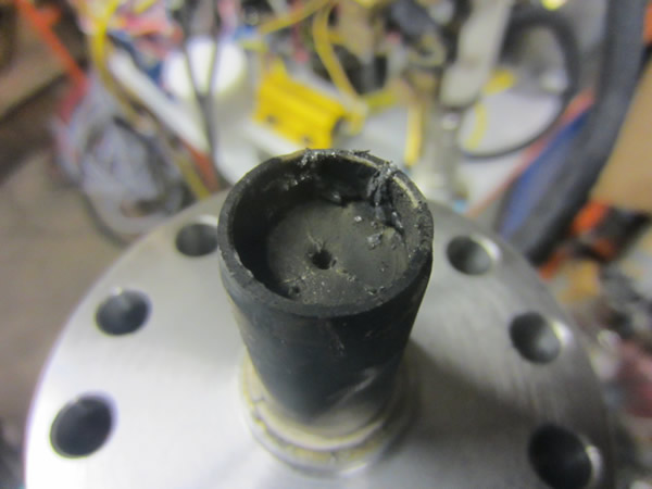
There is only an 0.05mm gap between the stainless tube and the vessel, the first picture clearly shows that the vapour must have had great pressure to move this far. The second picture shows the left electrode covered in aluminium residue, the brass face had clearly molten so I'm guessing that the plasma produced by the wire also caused some of the energy to discharge through the plasma between the brass electrodes.
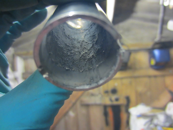
The inside of the stainless tube covered in aluminium residue, and then the right electrode also covered in aluminium residue. This experiment was also intended to produced some nano particles, aluminium nano particles ignite in air which could explain the second bang, did I manage to make nano particles?
Overall this project taught me the design of pressure vessels and the requirements to switch huge capacitive loads. I can't see me ever visiting a project such as this again as it's simply too loud, the main reason I did it in the first place is because the bank was discarded from a previous project.
Hello, if you have enjoyed reading this project, have taken an interest in another or want me to progress one further then please consider donating or even sponsoring a small amount every month, for more information on why you may like to help me out then follow the sponsor link to the left. Otherwise you can donate any amount with the link below, thank you!