Quad Turbo V12 with Semi Sequential 12 Speed Transmission
Yes, I'm nuts
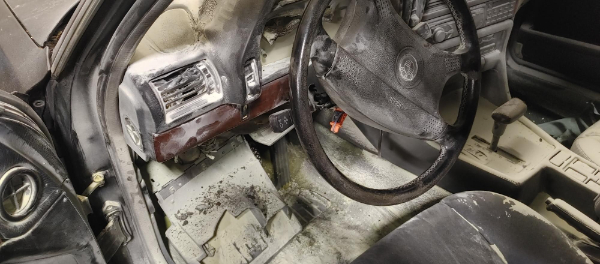
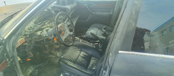
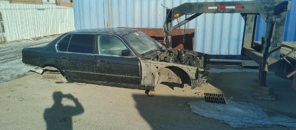
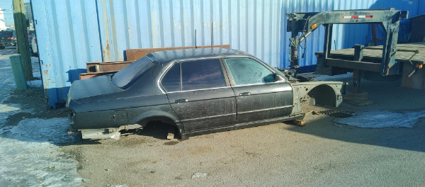
I came across a 1990 BMW 750 E32 that had fire damage on the dashboard, to cut a long story short the original owner set the front speakers on fire due to the audio system, which then burnt the whole dashboard. I managed to get it running within a couple of hours. I stripped the whole car bolt by bolt over the next 24 hours, there was a lot of stuff I was going to keep but in the end chose just the engine and front seats. I got some money back from the catalytic converters, so the engine sets me at $1200 CAD.
The engine is a BMW M70 V12 that has a displacement of 5L and around 300BHP. It is an all aluminium block with Alusil coated bores. While it doesn't make a lot of power stock it is quite a strong engine and responds well to boost. In the future I want to billet the whole engine, but for now I want to keep with the stock block and internals for financial reasons.
I will be making my own ECU from scratch to control the engine, along with two injectors per cylinder and an ignition coil per cylinder. The original uses two coils and two distributors for the whole engine, and one injector per cylinder. The engine currently has two intake manifolds with two separate electronic throttle bodies, originally each metered by a MAF sensor and each half of the engine controlled with it's own separate ECU. I plan to make my own intake going into one throttle body, cable operated. There are four exhaust manifolds on the original, I have not quite decided to keep these or not, but I will be mating them to four turbos. All of the turbos will have their own exhaust, but all the air outlets will tie together to go through an intercooler. The turbos for now will be from Volvo V70's, but that could easily change depending on donations. I'm aiming for a reliable 500BHP to begin with on very low boost, once I purchase a second back up engine then I'll see what it max's out at and blow it up.
The transmission is the very first thing I am going to design because that I can half prototype it in plastic first to prove the concept, and hopefully this is what may get me a following on social media. The original car only came with an auto and the manual in the 850 was very rare too, and auto's are far too boring. So the idea is to design and build my own sequential transmission, although at the time of writing this I already have. I will also be designing a twin disc clutch to accept the torque when I ramp up the boost. The transmission will use straight cut gears and dogs so that clutchless gear changes are possible. What sets it different / or a semi-sequential is that all of the shift forks are pneumatically controlled and it will have it's own control unit.
The amazing thing with the transmission is that you can change to any gear with the speed of a sequential. It will have 8 sets of gears which will equate to a 12 speed. The gear ratios as follows;
1st - 2.8,,,,,,,2nd - 2.444,,,,,,,3rd - 2.138,,,,,,,,,4th - 1.871,,,,,,,,,5th - 1.636,,,,,,,,6th - 1.429
7th - 1.225,,,,,,,8th - 1.069,,,,,,,,9th - 0.935,,,,,,,,,10th - 0.819,,,,,,,11th - 0.716,,,,,12th - 0.625
Here is the problem with the design. As you change the ratio's of gears you will end up with a smaller gear at one end and a large gear at the other. This doesn't sound like much of an issue of the large gear but the smaller is more of an issue as it gets weaker. Nearly all of the gears in a transmission have the output shaft or the idler shaft in common, so to translate the power through all of the shaft you don't want to make it smaller.
Now the average 6-speed transmission will have six sets of gears that can change, the difference between my design is that it has a high and a low change on the input shaft, that means 2 x 6 gears, which is where the 12 comes from. The biggest issue is the change from 6th gear to 7th gear as you want the ratio's to change by similar amounts. To get this to work with a minimum and maximum size of gears it means the overdrive is quite small. The bonus with this transmission is that I could skip gears if the ratio's are too close to each other.
The bigger question is why no one has made a transmission with this many gears. Well they have, that is in diesel trucks with small power bands. The whole point of changing gear is to keep the engine in the power band. With an engine that has lots of power it doesn't matter too much because traction will be the limiting factor. With a low power engine you want as many gears as you can to be in the optimal range.
Lastly, why? that's because why not?
One more update, I have changed the design slightly so I can use a different set of gears, I think I've nailed it.
1st - 2.8,,,,,,,2nd - 2.2857,,,,,,,3rd - 2.138,,,,,,,,,4th - 1.871,,,,,,,,,5th - 1.243,,,,,,,,6th - 1.00
7th - 1.00,,,,,,,8th - 0.816,,,,,,,,9th - 0.668,,,,,,,,,10th - 0.546,,,,,,,11th - 0.440,,,,,12th - 0.357
It may seem a little strange that 6th and 7th gear have the same ratio's. For one the transmission can skip gears, so from 5th to 7th for example, there is another reason but that's easier to explain with a demonstration. I can yak on all day about it, mostly importantly this gear set has a low 1st and a very high overdrive in 11th and 12th.
One last thing of straight vs helical gears and why one or the other. Helical gears are stronger, mesh smoother and are a lot quieter. The problem with helical gears is they want to push away from each other axially, this pushes against the walls where the bearings sit. This can lead to high bearing wear, failure or even the transmission casings cracking or breaking. The straight cut gear doesn't push axially and can be a little more efficient. Straight gears are very noisy as the teeth are smashing into each other, so they need to be built slightly beefier to make up for it. The main reason I'm going for straight gears is because they're much easier to make, especially if you don't have the right machinery.
Current Progress
This part will be more of a project log,
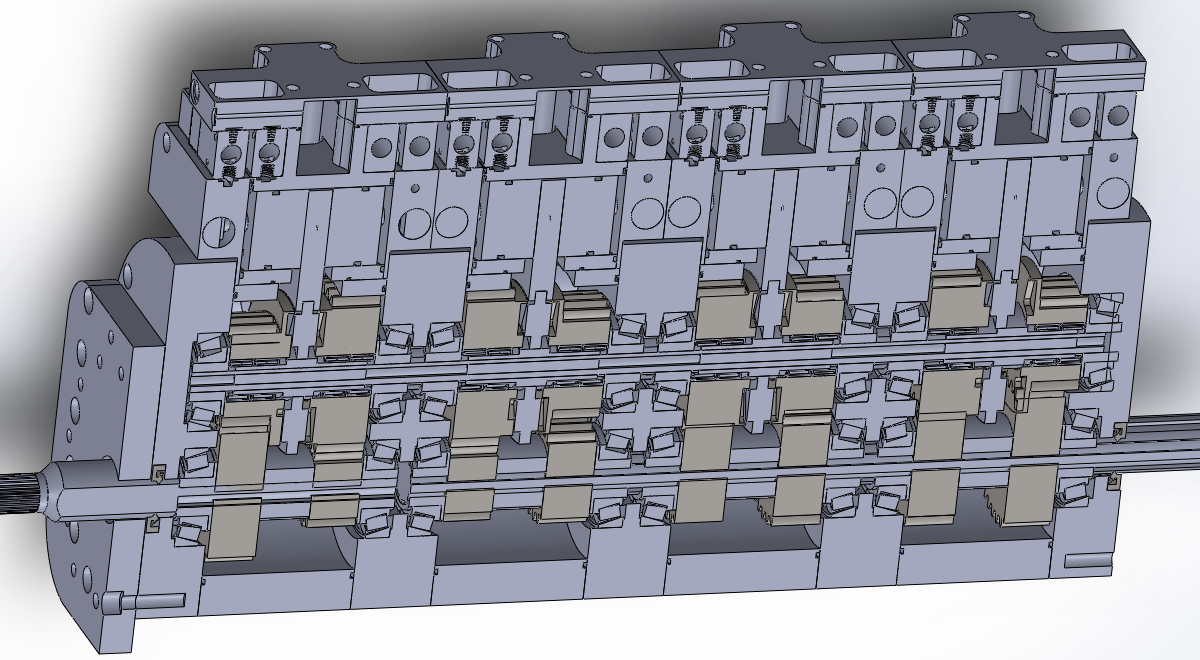
Here is the current progress where I'm at with the design, which is pretty much done. This is what happens when you take 3 days off over Christmas, :).
The most complex part is probably the shifting forks as there are some blocking rods that stop it at the middle position, to stop it engaging the opposite gear on the fork. Overall there are 16 pneumatic solenoid valves which control all of this, all supplied by a common manifold with buffering tanks. It may sound complex but it's a fairly easy system to control. The most important thing is that many parts are the same to add a little less complexity, in fact the only parts being different are the gears themselves.
I have a couple of ideas with the gears themselves as they cannot be made on a gear hobb or a milling machine, making them as a single piece will ensure they are strong.
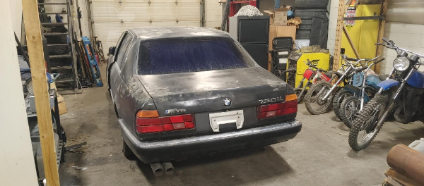
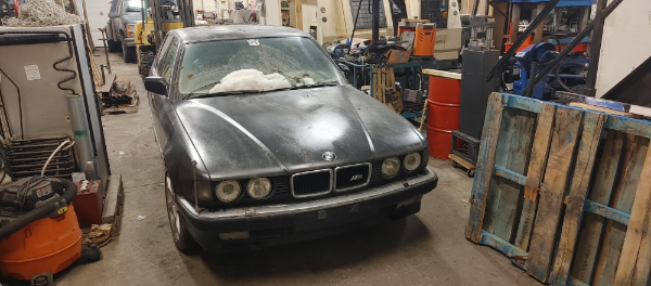
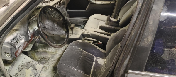
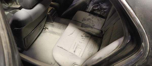
Here are a few pictures of the BMW that I bought along with the process of tearing it apart. If the original owner didn't decide to repaint the car and make such a bad job of it then I would have likely kept it. There wasn't a single dent, the interior in excellent condition, apart from the dashboard and all the fire extinguisher dust.
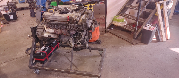
Here is the stand that I made so I could wheel the engine around, and of course later run it. I chose to go with two batteries, one just for cranking the engine and the other for everything else.
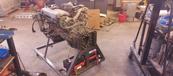
2-Jan-2024 - I started writing this page after spending the last three days designing the transmission. I bought the car over 9 months ago and stripped it in 24 hours over the weekend. I didn't feel like I had the time at all to work on this project, but after a couple of bad decision, poorly paying customers, etc... I realised that I had done nothing but work and didn't do a single thing for myself. I am now at the stage with my business where I have got nearly all of my machines working (I buy them fairly cheap to fix, CNC's are expensive!). I still have quite a bit of money to earn and need to spend some time fixing my newest CNC mill, after that I will be doing a lot of work on this engine.
Progress is all dependant on my income and the expense of material for what I'm building. Making a fuel tank, the coolant tank, battery terminals and some basic electronics isn't all that expensive, most of that being time. The transmission however has quite a number of bearings, a lot of aluminium and a lot of time. I have started with social media again to hopefully get a backing, every little helps. There will be this project, my dirtbike, maybe my daily driver and the odd other bit. I don't really have the time to make video's for my everyday work, but will assign one day a week to this, all depending on popularity I'll be able to spend more than one day a week.
Today I assembled the model to my running cart. I still have the engine to model, but I may be able to borrow a 3D scanner to capture the outside of it. I'm a long way of doing a billet engine, so don't want to start pulling it apart.
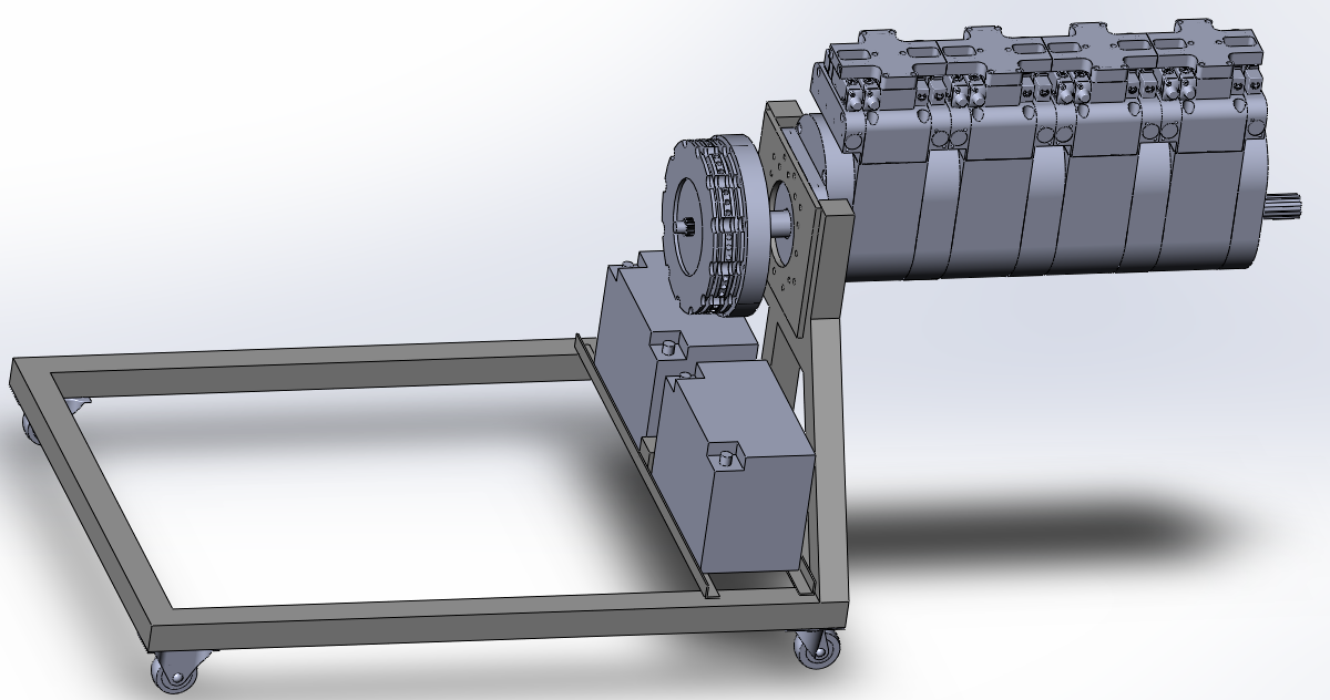
I still have a small amount of design work to do on the transmission, that being the lubrication system. Since the inside is fairly long and each section is almost gated from one another it makes the lubrication a little more difficult. I could cut out a slot in the end plates so that the oil can flow from one end to the other, the problem with that is lack of oil due to acceleration or braking. I'm going to make a dry sump system so that there is little friction on the gears due to oil submersion, plus there will be a pump to drain each section making g-forces irrelevant. I'm not sure there is a single manual transmission out there that uses an oil pump, but mine has a lot more bearings and I don't believe splash lubrication will be sufficient.
If I place an oil orrifice in the center where four of the bearings meet then all of them will be lubricated sufficiently. There doesn't have to be much pressure, just enough to push it through the passages. It's doubtful that I would be able to move enough oil through the bearings to spray on the gears, so there will be a sprayer pointing in the center of each meshing point. The oil pump won't have to flow much at all, so I'm wondering if it's possible to integrate it into the design. That I have not chosen, but there are a few mechanical options. I need to consider that if in neutral then only the input shaft is spinning, but if the clutch is held in then the idler and output shaft will be spinning, assuming the car is free-wheeling. There is also the option of using an electric pump, but I need to consider it will require several pump bodies for the scavenging of the sump.
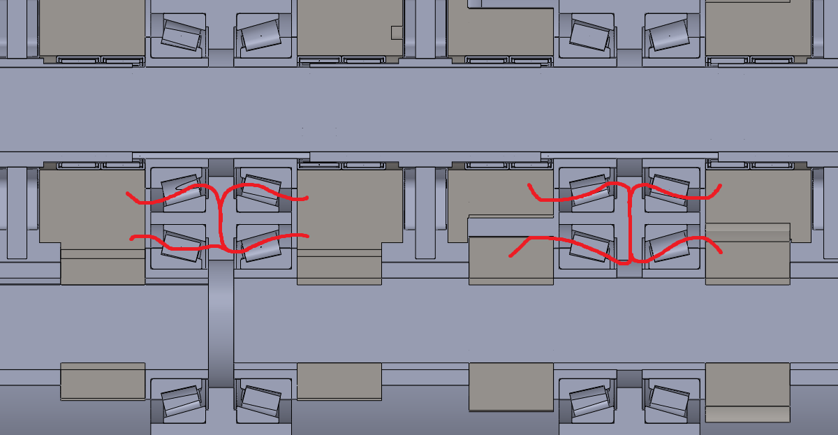
One last thing, you may also notice that there is no reverse gear. This is again something I've thought about but not sure how to execute it yet. I am thinking an extra section on the front of the transmission that includes an extra gear between that and the idler shaft. I didn't want to make the transmission too much longer, but that will give me some space to place an oil pump too.
One last update for the day. I ordered a bunch of 3D printing filament so I can make a working version of this transmission long before the metal one, it's just so much cheaper. The one thing that could be a problem is the pneumatic actuators for the forks might not work properly, so I might have to make a couple of bits in metal. The main expense is the housing sections and the bearings, both of these I can 3D print to trial.
Parts List
There are lots of parts to buy and a bunch of raw materials. I'll list them all with an estimated cost. I will of course be making as many parts as I can myself with the sacrifice of my own time. There are some parts that are simply not viable, such as the bearings.
BMW M70 Engine (98,000kms) - Qty 1 - ($1200 CAD) - Bought - By Me
32210 SKF Taper Roller Bearing - Qty 16 - ($800 CAD)
HK4520 SKF Needle Roller Bearing - Qty 16 - ($720 CAD)
Input/Output Shaft Spline 4140 Stock - Qty 2 - ($830 CAD)
Pneumatic Solenoid 5/2 Valve - Qty 16 - ($370 CAD)
At a Guess $4k CAD in material to make housings and gears.
End Goal
I'm not entirely sure there is an end to this project, but there are some check points I want to hit. So here is a list of them.
V12 Engine running on my own ECU, with fuel tank, coolant tank, stock intake.
Engine flywheel mated to clutch.
A working 3D printed version of transmission
A working metal version of transmission coupled to engine, all working.
Quad turbo time.
Get a 40/50's truck or car to put it in.
Have some fun, max out the boost, blow it up.
Complete billet engine, modular design (V6, V12 or V18)
On a side project I always wanted to make a modular engine, that was originally going to be a V4. The idea was by keeping an engine small you can keep the crank pretty light weight and aim for high rpms. The engine would then link to a central shaft by gears. The idea is that many engines could be bolted to this main shaft and when something fails it's not a big part. I would rather make four crankshafts than one large one, plus I'm limited to the machinery I have access to. I would be looking to make everything myself, but I might also design it to make use of already existing engine parts out there, especially rods and pistons.
Sponsors / Donations
I will list everyone who has donated including the amount, of course people can remain anonymous. I'll put the list in order of amount, the best donations to the top.
No one yet
Hello, if you have enjoyed reading this project, have taken an interest in another or want me to progress one further then please consider donating or even sponsoring a small amount every month, for more information on why you may like to help me out then follow the sponsor link to the left. Otherwise you can donate any amount with the link below, thank you!