Microcontrollers 7 - Memory and Addressing
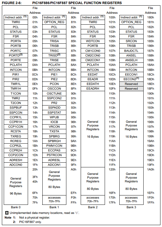
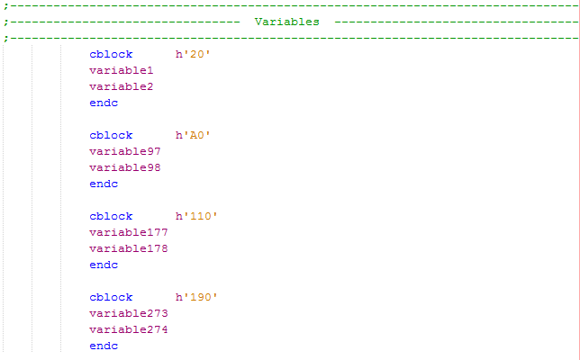
Firstly I will talk about variable memory, the "cblock", and RAM which are all the same thing. As you've noticed throughout these chapters you can easily write what you want into the file registers along with RAM, that's because they are part of the same memory block. The special function registers are those that we write to set the options of the microcontroller, they can all be written and are forgotten when the chip powers down, this is because they are RAM. The general purpose registers are the locations we save the variables to, as you can see in the diagram below there are four spaces where the RAM is stored, one in each bank. At the start of the program we define where we want these variables to be written from, so when we specify h'20' that means to start writing the variables from that location in bank 1. Shown in the section of code on the right shows how we would write the variables to each of the RAM locations, easy as that.
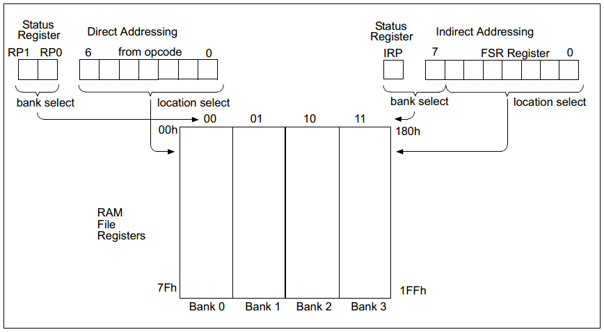
Now there are two terms you may have come across; direct and indirect addressing. Direct addressing is used in the initialisation process at the start of the program, it is where a memory bank is selected, then a particular register for something to be done with it. On the other hand indirect addressing is done by using a specific register that selects a register by loading it's address, a seperate register will hold the contents. The difference between the two is that direct addressing is normally used for special function registers whereas indirect addressing is used for the general purpose registers - RAM.
So why use direct addressing in the first instance. Direct addressing is useful for dealing with just one particular register, like with the special purpose registers all have different meanings which have to be directly addressed, it is normally when their individual bits have to be set such as that with the status register. Using indirect addressing is used for the variables as a location can be loaded into one register and the contents presented in another register, it saves a lot of steps and is very useful for storing data. To sum up direct addressing is useful for setting bits in a register whereas indirect addressing is useful for whole bytes of a register, it is also a lot quicker when dealing with multiple registers in succession as you will soon find out.
In the last chapter I used a keypad to save a value into a variable and then display it to an LCD. What if I want to be able to save maybe ten digits into the variables. One way would be to directly address a variable by saving the contents from the keypad into it, the next character would then be placed in the second variable, the program would have to check the contents of the first variable to ensure it had been filled before writing to the second, the only problem is that if zero is placed in the first variable how would the program know. This way is no good at all and this is where indirect addressing has it's place. With indirect addressing there are now only two banks, the first covers bank zero and one, the second covers bank two and three. The "IRP" bit in the status register selects between banks one or two, since most of the file registers are in the first two blanks it can be left zero. All that is needed for indirect addressing are the "INDF" and the "FSR" registers which as you can see are situated in all of the banks.

The "FSR" (File Select Register) is used to select a particular address, so for example if the value of h'20' was to be placed into it then it would select the first general purpose register. The contents of this register would be displayed in "INDF" (Indirect Addressing File), these contents are read / write-able. Below is a section of my program that will save the read keypad value into ten variables.
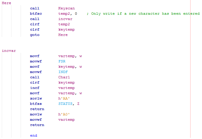
This part of the program is same as the last except instead of sending a character to the LCD it calls the program "incvar" instead.
Firstly "vartemp" is a variable I saved at the start of the program with the value of h'A0' as this is the start block of the RAM in bank 1.
This value is placed in the "FSR" and the value of the contents are read from "INDF", the LCD is updated. "vartemp" is incremented so the next time it loops it will save a variable in the next RAM location, h'A1'.
The value h'AA' is compared to "vartemp", if they match then the RAM start location will reset back to h'A0' if not then it will return ready for the next keypad input to increment the RAM. There is a difference of ten in the above hex numbers, to store 10 variable values.
The LCD program also need to be changed to display all the ten variables, it's best not to directly address as this would create a larger program.
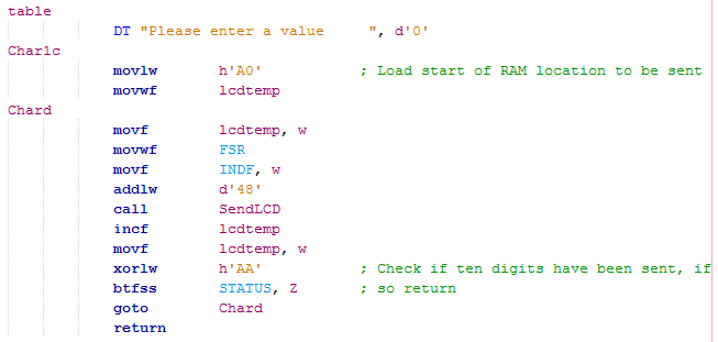
Firstly h'A0' is loaded to "lcdtemp" as this will tell the "FSR" what the start location of the RAM will be.
The contents in "INDF" are loaded to the working register to have the value of 48 added to convert the number to ASCII, this value is sent to the LCD.
The RAM location folder is incremented and then checked to see if it has been incremented a total of ten times, if not it will loop around to send the next character to the LCD, if it has then it will return from where it left off.
Without indirect addressing "Chard" would have taken 21 instructions to complete.
Finally one other change I had to make to the start of my program was to set these new variables to zero, instead of listing them all and clearing them by direct addressing I can clear 64 variables with only seven instructions. The program loads the "FSR" with the start location of the RAM variables I want to clear, the contents of the variable is then cleared in "INDF", the "FSR" is incremented again to have the next variable cleared. When the "FSR" reaches 64 it will skip, to clear the 80 bytes available from this location would only require a few more commands although not needed in this example.

I mentioned earlier about something call a page boundary, it is basically each 2k of data in the program. Since the 16F628A only has 2k of memory then these don't apply however after the next chapter I will be upgrading to a larger chip with more memory.
Here is the program with the added changes, you can take a copy of it from here - Program

Below is an example of the output, when the keypad is pressed for the eleventh time it will rewrite the first digit on the display.
A series of digits can be placed in the variables but when powered off these values are lost, they are saved in RAM which is volatile. The next chapter will concentrate on saving these values in the EEPROM to set and check a password, due to EEPROM being non-volatile the data will be retained when power is lost.
Hello, if you have enjoyed reading this project, have taken an interest in another or want me to progress one further then please consider donating or even sponsoring a small amount every month, for more information on why you may like to help me out then follow the sponsor link to the left. Otherwise you can donate any amount with the link below, thank you!