Paddle Shift for Automatic Transmission
At the time of writing this (April 2017) my car is a 98 Hyundai Tiburon Auto, it was cheap ok. I don't have the space to fit a manual transmission yet even though I do have one. This is my first auto car and I really hate it, the largest problem is that it's so unresponsive and changes gear at the totally wrong time, it does sometimes jump down two gears which is sometimes a little scary.
The point of this project is to make a computer that controls the automatic transmission and then some kind of a paddle system allowing me to change gear. I will also include some extra's which does a "soft" or "hard" gear change dependant on throttle position, a program that locks the torque converter at a certain speed and finally a program that only allows a down-shift at a maximum rpm.
The first step was to see how many solenoids control the transmission, below is an excerpt from the workshop manual.
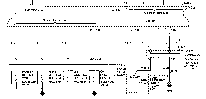
A total of four solenoids is pretty standard for the older electronic 4-speed transmission, some do have upwards of eight. So in basics there are two main solenoids to control the gear pattern ( solenoid A and B ), a third the pressure control value to control how fast the gears engage and finally the damper clutch solenoid. The damper clutch solenoid locks up the torque converter, the reason to do this is because there is always a percentage of slip, more at lower rpm's which leads to heating and of course wasted energy. Locking the torque converter is generally used for highway driving or anything above say 80km / h to reduce heating.
The pressure control valve is linked to the shift solenoids in that it regulates the oil pressure to them. When cruising you want to change gently in which the pressure solenoid activates removing oil flow to the shift solenoids, the gears shift, the pressure solenoid releases and the gears "gently" change. When "hard" accelerating the pressure control solenoid remains dormant. Sometimes the pressure control solenoid is powered via PWM (Pulse Width Modulation) which can apply the pressure back in a more controlled manner.
The shift pattern of control solenoids A and B can sometimes be a little guesswork since the manuals generally don't tell you. What they do tell you is that when the shift module is disconnected that the car will remain in 3rd gear, this means that both A and B off will be third. I constructed a truth table based logically. Following this truth table only one solenoid changes it's state between gear changes, this table is correct to my transmission.
| Gear | B | A |
|---|---|---|
1 |
1 |
1 |
2 |
0 |
1 |
3 |
0 |
0 |
4 |
1 |
0 |
The next step was to find out what the wiring was in the car, below is the transmission control module.
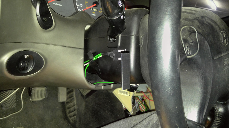
It has two connectors, the larger connector can be disconnected as this controls the solenoids and reads sensors that are generally not needed. The smaller connector reads the transmission speed which then controls the speedometer, this needs to remain where it is. The workshop manual told me what each of the pins in the connector does so it was pretty easy to splice into the wires that I needed. I also had to splice into two wires on the smaller connector, the speed and engine rpm outputs. Below shows the spliced wires and my connector that I will use for my shift control module.
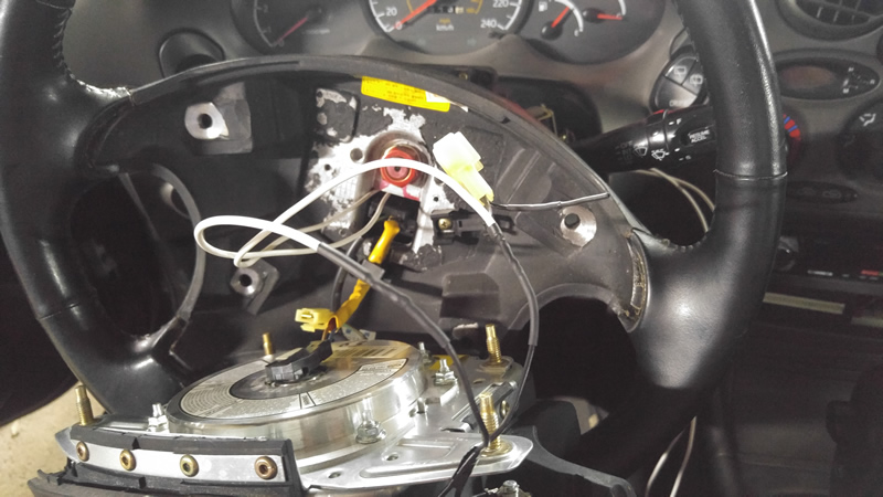
The next step was to find some control buttons for the shifter, luckily I had two horn buttons so I used these to shift.
I mocked up the circuit on a breadboard using relays to control the solenoids as shown below. (The display and keypad are part of another project)
So did the prototype work? well yes and no. Using the horn buttons was a bad idea since the wires wrapped around the steering column which was expected. I chose to reconnect the horn and instead chose to pursue a paddle shifting system instead - 3D printing.
I did a few measurements around the steering column, these paddles are only temporary until I fit the manual transmission so they don't have to be anything special, I will use sticky pads to hold them in place. So firstly I came up with a paddle design.
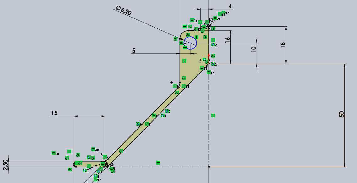
Then gave it depth, the final result.
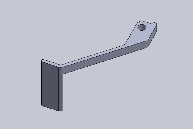
Then created the G-code for the printer.
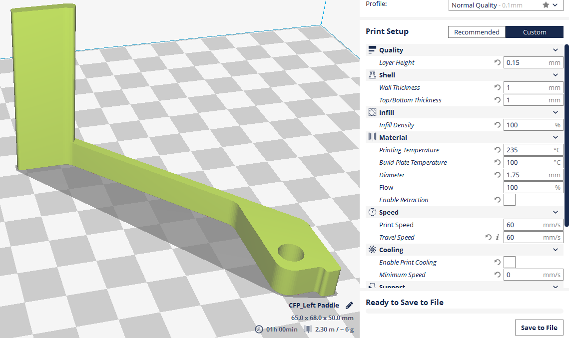
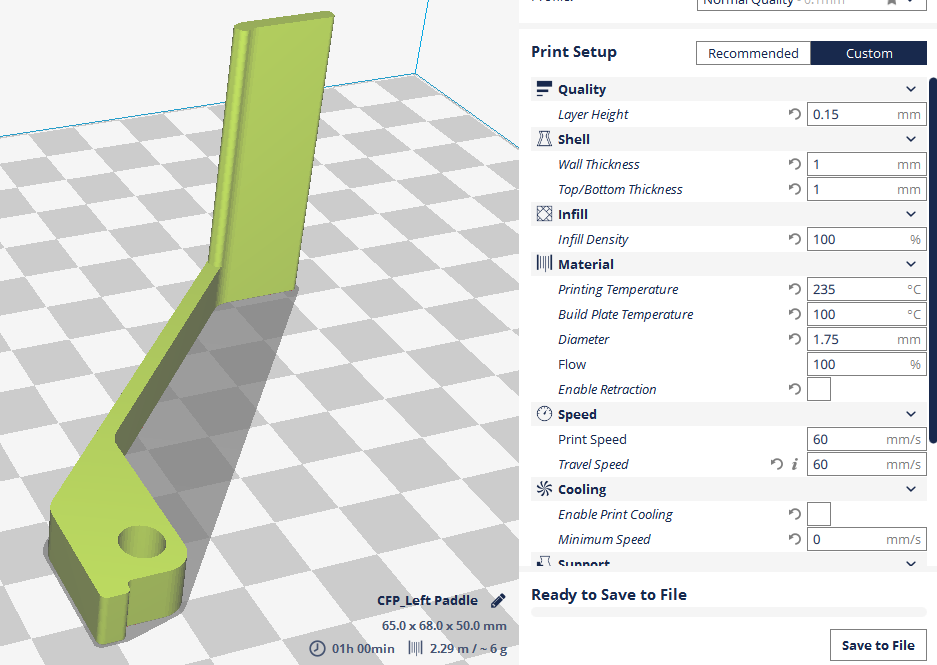
Then the right paddle using the mirror function.
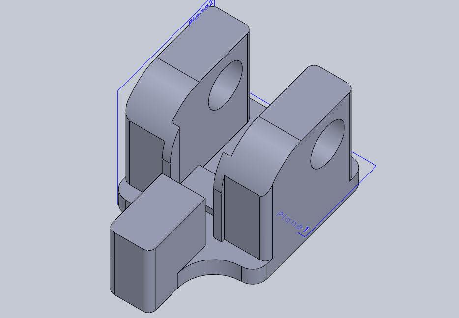
The next step was to design a block that would allow the paddle to pivot and house a switch.
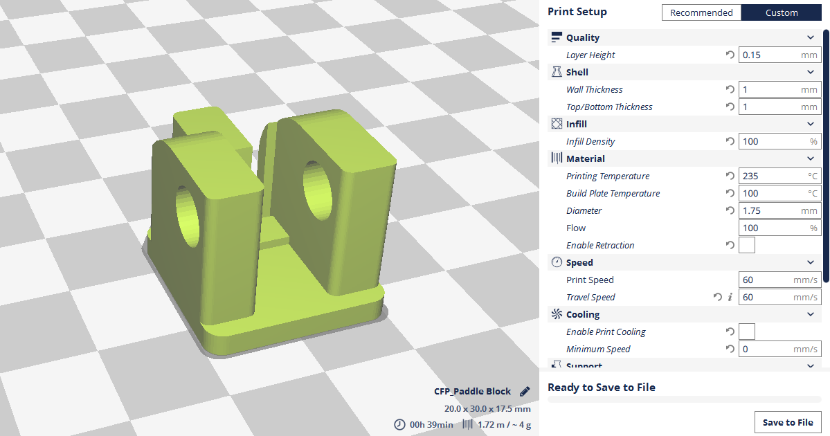
Creating the G-code for the block.
With the addition of a pin here is the final result assembled, both the left and right paddles. The right image shows the prototypes that I went through to perfect them.
I soldered on the wires and using a sticky pad installed the paddles to the steering column.
The computer was the next thing to design, I chose to go with the PIC18F24K40 since they're so cheap and they can run at 64MHz if I choose to link them with my ECU's SPI, that's a big if. The first step was to create a board, here is the design a came up with, luckily it has only one jumper and I managed to keep it single layer.
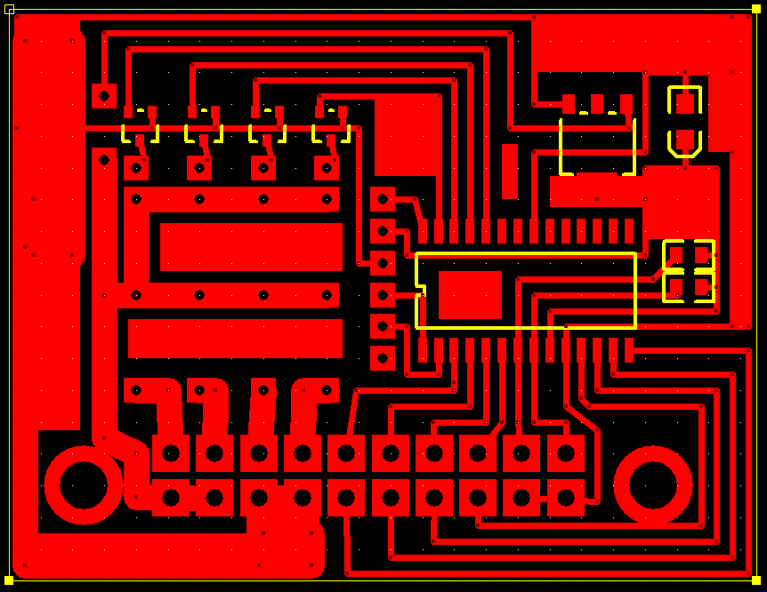
The board printed and drilled, I'm trying to stray away from holes and go for surface mount, the only exception in this case is for the connectors and relays.
The board complete, the ICSP header for me to program the board.
I then chose to 3D print an enclosure for the board, if the module works perfectly I will fill it with resin as I won't need to program it again.
Well did the module work ? Well yes and no, the back emf from the solenoids destroyed the chip. I left the project for another month and set a time to convert my car to manual transmission, with this in mind I chose to re-design the controller and start again. Here is the board layout using a different chip this time, just a 16F628A.
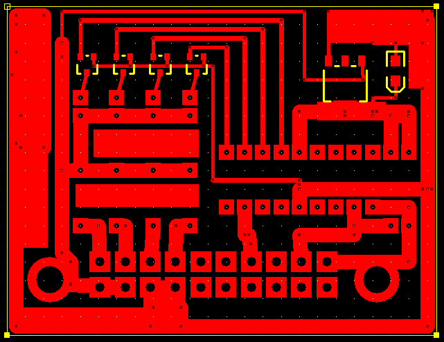
I chose to drop most of the features in the program and set to making it read the paddle inputs and control the solenoids, that was it. I also threw loads of diodes on the board as a quick fix to protect the chip from back-emf.
The controller worked perfectly, the order of shifting, 1, 2, 3, 4 and then torque converter lock up. I drove it for a week and it worked a lot better than the previous automatic control. The downshifts had to be rev-matched but apart from that it was very smooth, unfortunately I didn't get a video as I got impatient and converted my car to manual transmission.
Here is the program;

Hello, if you have enjoyed reading this project, have taken an interest in another or want me to progress one further then please consider donating or even sponsoring a small amount every month, for more information on why you may like to help me out then follow the sponsor link to the left. Otherwise you can donate any amount with the link below, thank you!