3D Printed Engine Bay Bracket
In other projects I have been working on my car with creating an engine control system. A piece of conduit tubing goes from inside of the interior to the engine bay, this bracket is to secure the tube at the other end.
Below is an example of why I need the bracket.
The software I like to use for 3D design is Solidworks, I have the 2016 edition. The first step is the base, the thing I like about this software is that dimensions can be driven and that multiple points can be changed via only one dimension. The hole is for a bolt to secure this bracket to the inner wing.
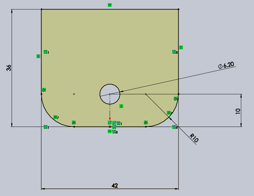
The base is extruded.
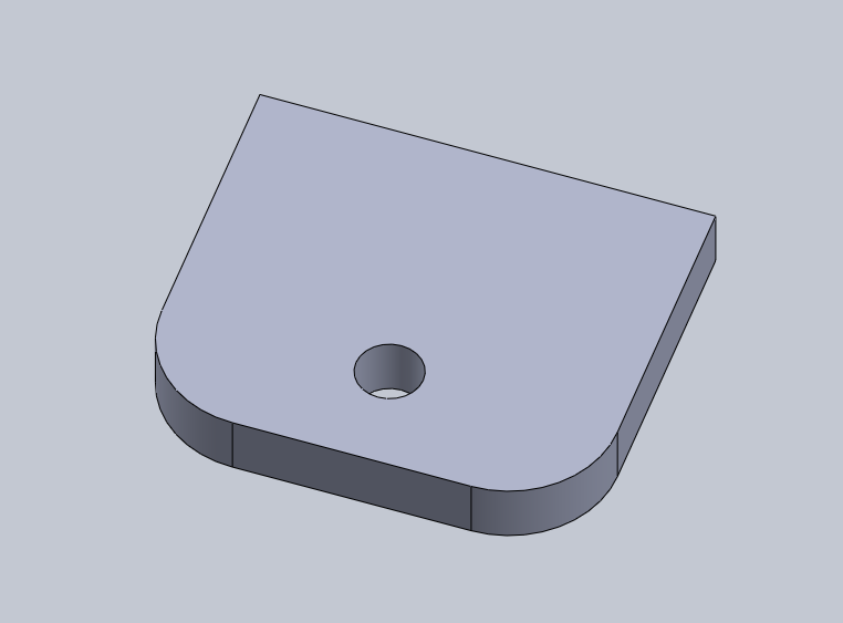
A plane is created on the back of the base in order to draw the vertical.
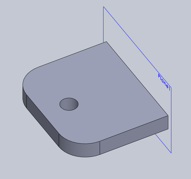
The vertical part is drawn, this is where the conduit tube will screw into.
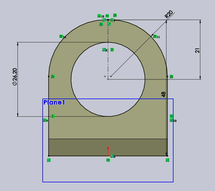
The part is then extruded.
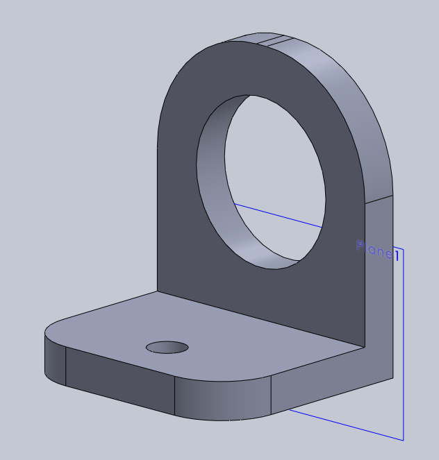
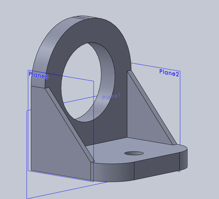
A plane is created on the side of the bracket.
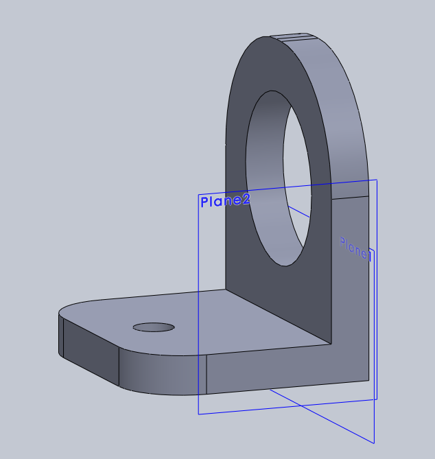
A support is drawn on the plane.
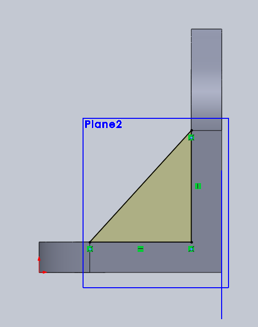
The support is extruded.
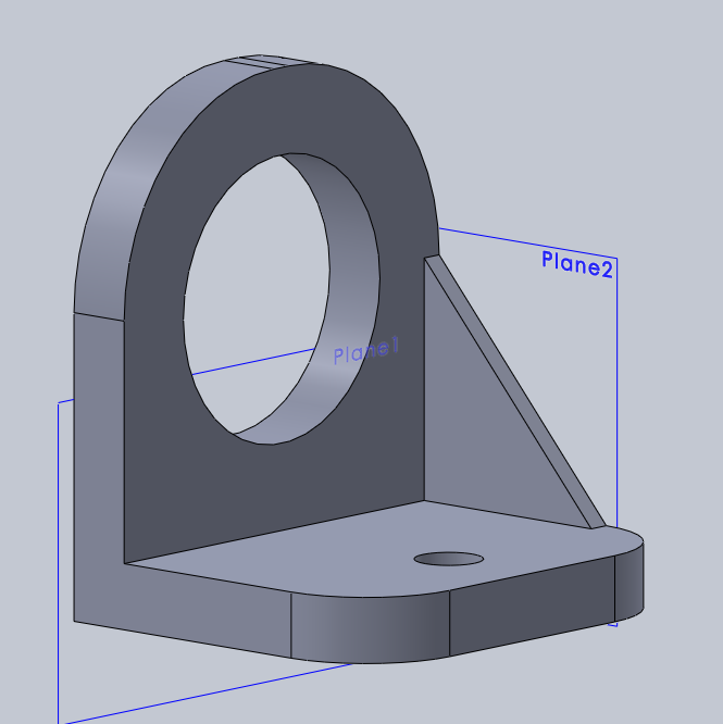
A second support is drawn. Since 3D printed parts are weaker than traditional injection moulded parts it is necessary to included these supports for added strength.
The G-code is created using Cura.
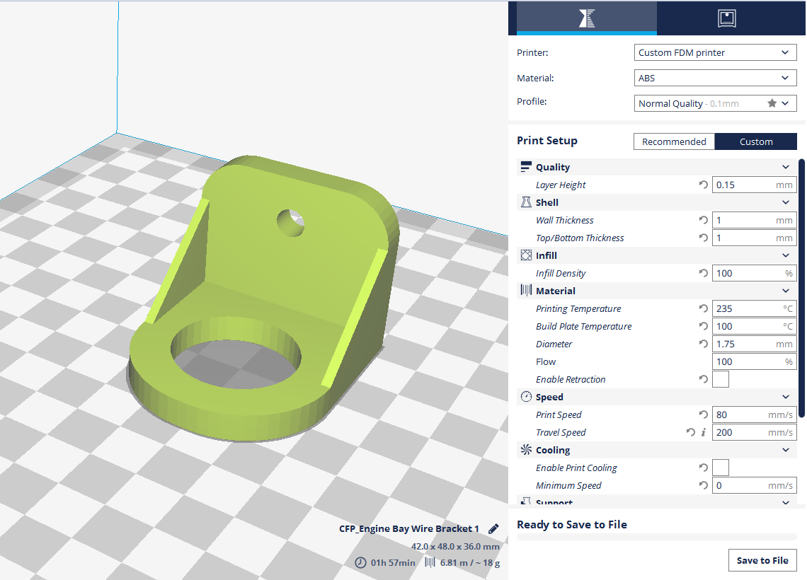
The part is printed which takes around 2 hour to complete.
The conduit pipe fits perfectly into the bracket.
Another picture of the finished bracket.
The bracket installed in the car, it worked perfect.
Hello, if you have enjoyed reading this project, have taken an interest in another or want me to progress one further then please consider donating or even sponsoring a small amount every month, for more information on why you may like to help me out then follow the sponsor link to the left. Otherwise you can donate any amount with the link below, thank you!