50,000V Fly Killer
I bought a 50,000V power supply with the intent of modifying it for the nuclear fusor project, instead I thought I would have some fun. I really don't like flies, especially mosquito's, and I believe most people feel the same. When I was younger I used to have an electric fly bat that would kill small flies, but would often get clogged or not deal with a swarm of flies. I know these kinds of products need to be relatively safe for the public, my project doesn't have to be.
Here is the power supply I have below showing a couple of arcs, these are constant.
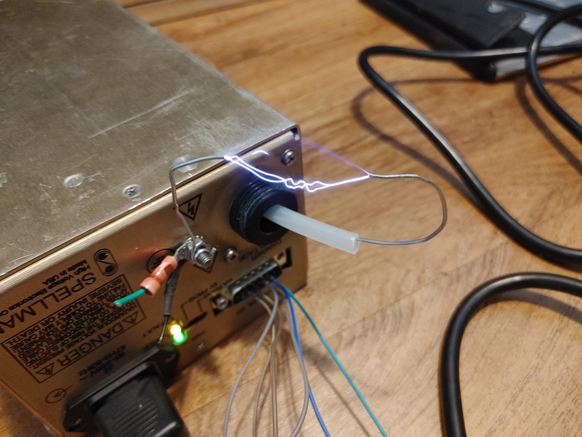
The general rule is that a spark will jump 1mm per kilovolt, which the above image justifies. The power supply is in fact variable allowing me to control the spark, or have no spark at all. If I am to place the grids at sufficient distance so that whatever chooses to fly through will not get stuck, but will close the gap enough to get electrocuted. I can move the setup through a swarm of flies and it will continue to work. It may not kill them all but it will be more effective.
The arc itself can also vary on the humidity and atmospheric pressure, so a variable supply will be vital. The grids themselves don't have to be anything special, I will go with 2.4mm TIG welding rods to keep it rigid. The power supply is rated at 1mA so should not be lethal, I however do not think it would be pleasant to touch. I have considered adding a capacitor to make it more devastating, that however could prove lethal to me, so I won't for now.
I spent a little bit of time coming up with a design. The grid will be 400mm square on the inside and spaced 30mm apart. The electrodes will protrude either side of the frame and connect to the power supply at the bottom. The supply itself will be housed in a box, there will be a potentiometer to control the voltage.
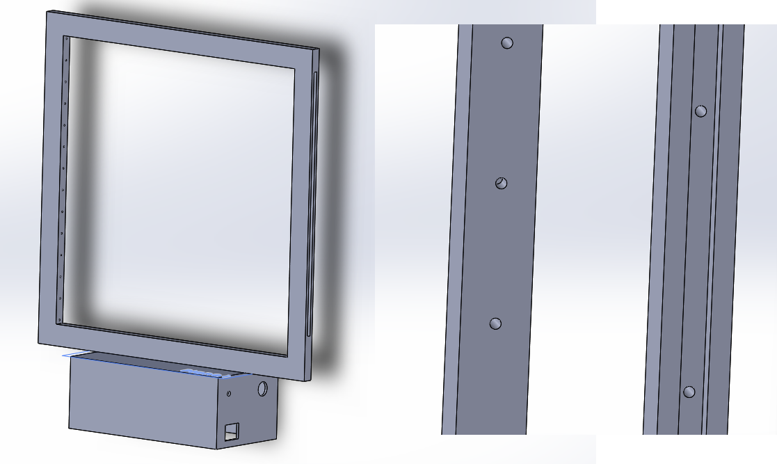
The whole of the frame will be 3D printed in PLA to make it cheap. Since it is such a big design I will have to split it into smaller parts to print. The very first part to print will be the housing for the power supply.
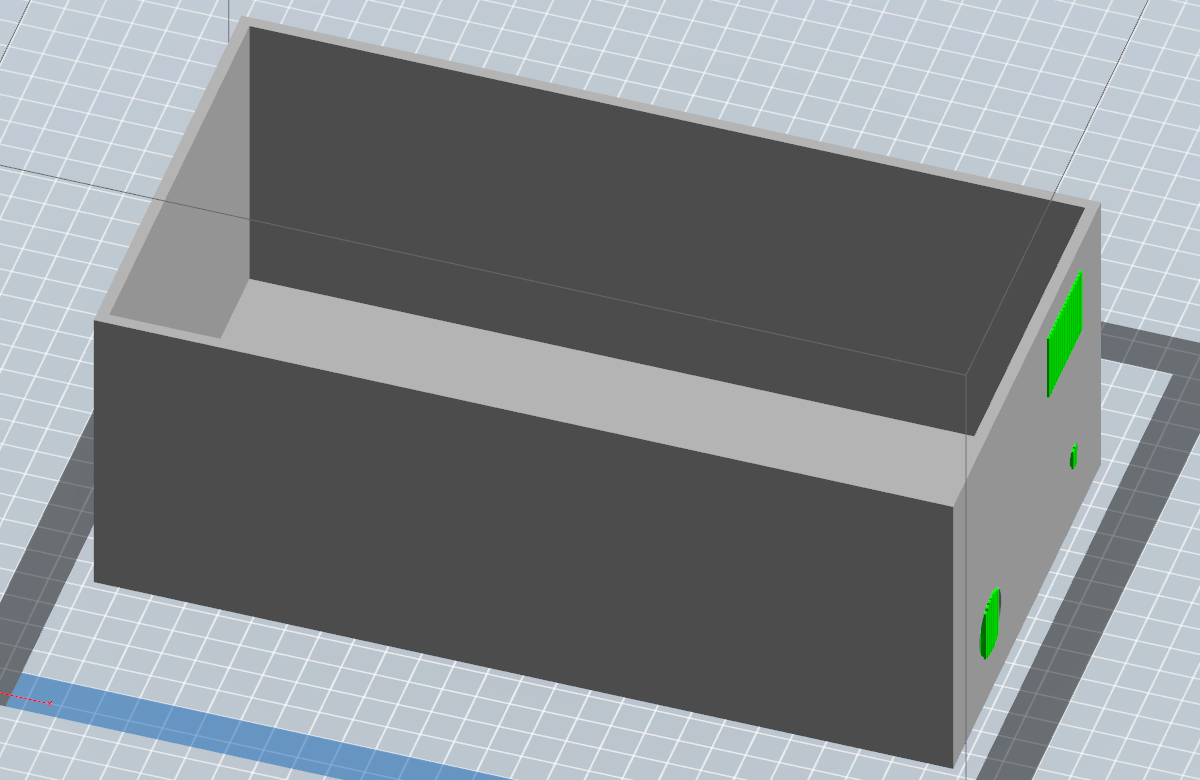
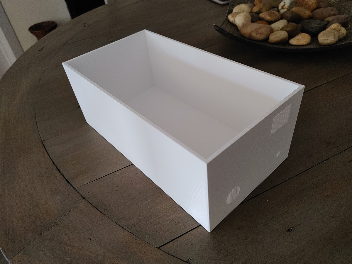
Here is the case printed in PLA, it came out really good.
Next a cap for the bottom of the housing, this will be glued in place.
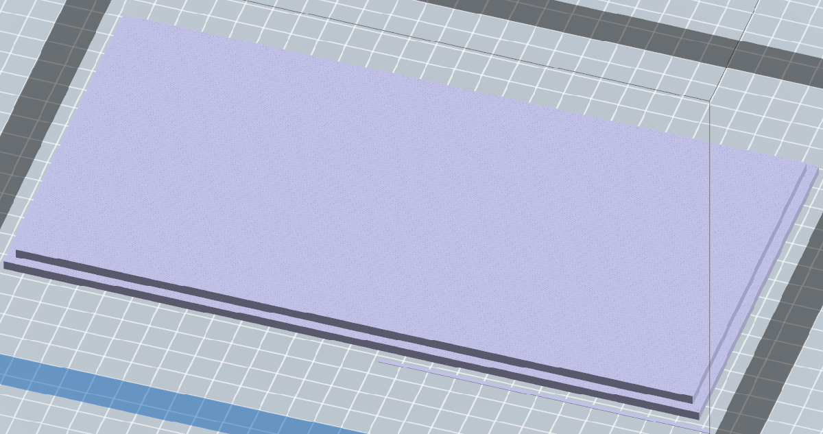
Here is the cap, I printed it in the wrong colour by mistake.
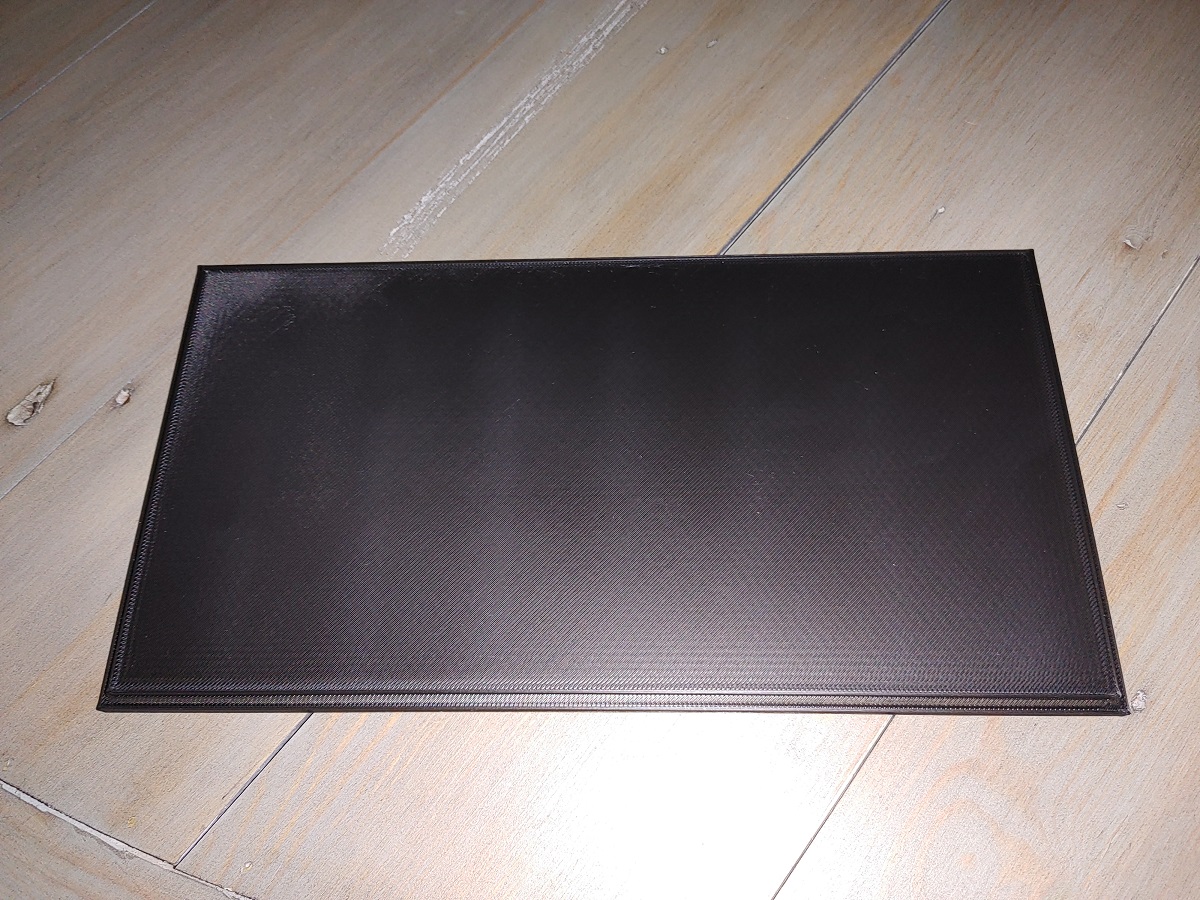
Next is the grid frame, this I had to cut into four parts to fit it onto the printer.
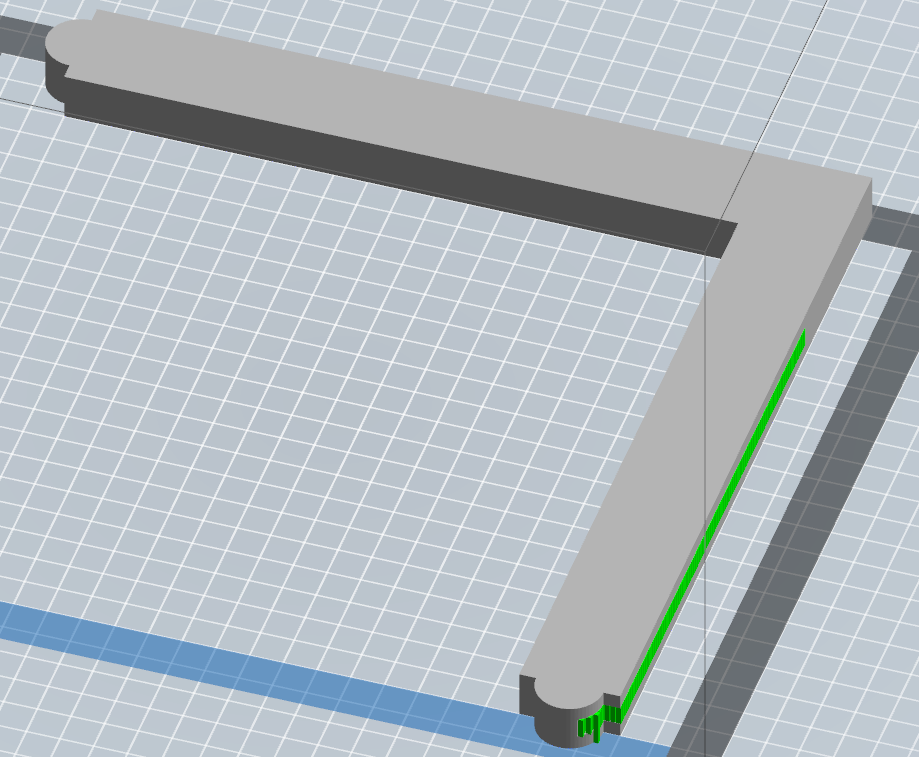
It took a bit of time to print all of these as I could not fit all on the printer bed. These will all be glued together.
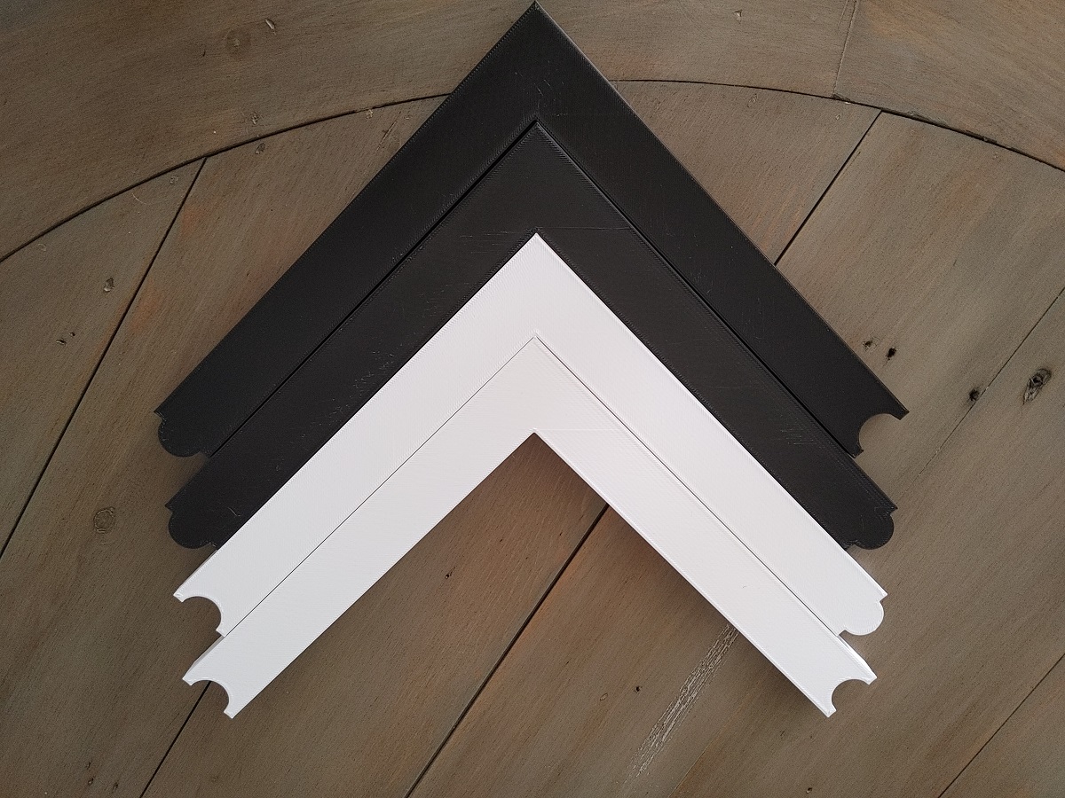
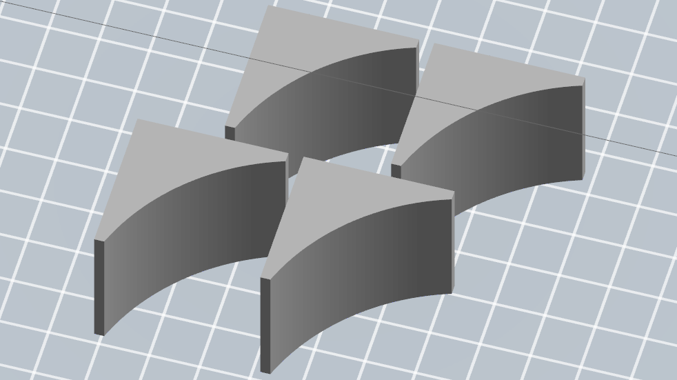
The last part to print which I did not show in the original design are a couple of wedges to support the frame better, these will be glued in place.
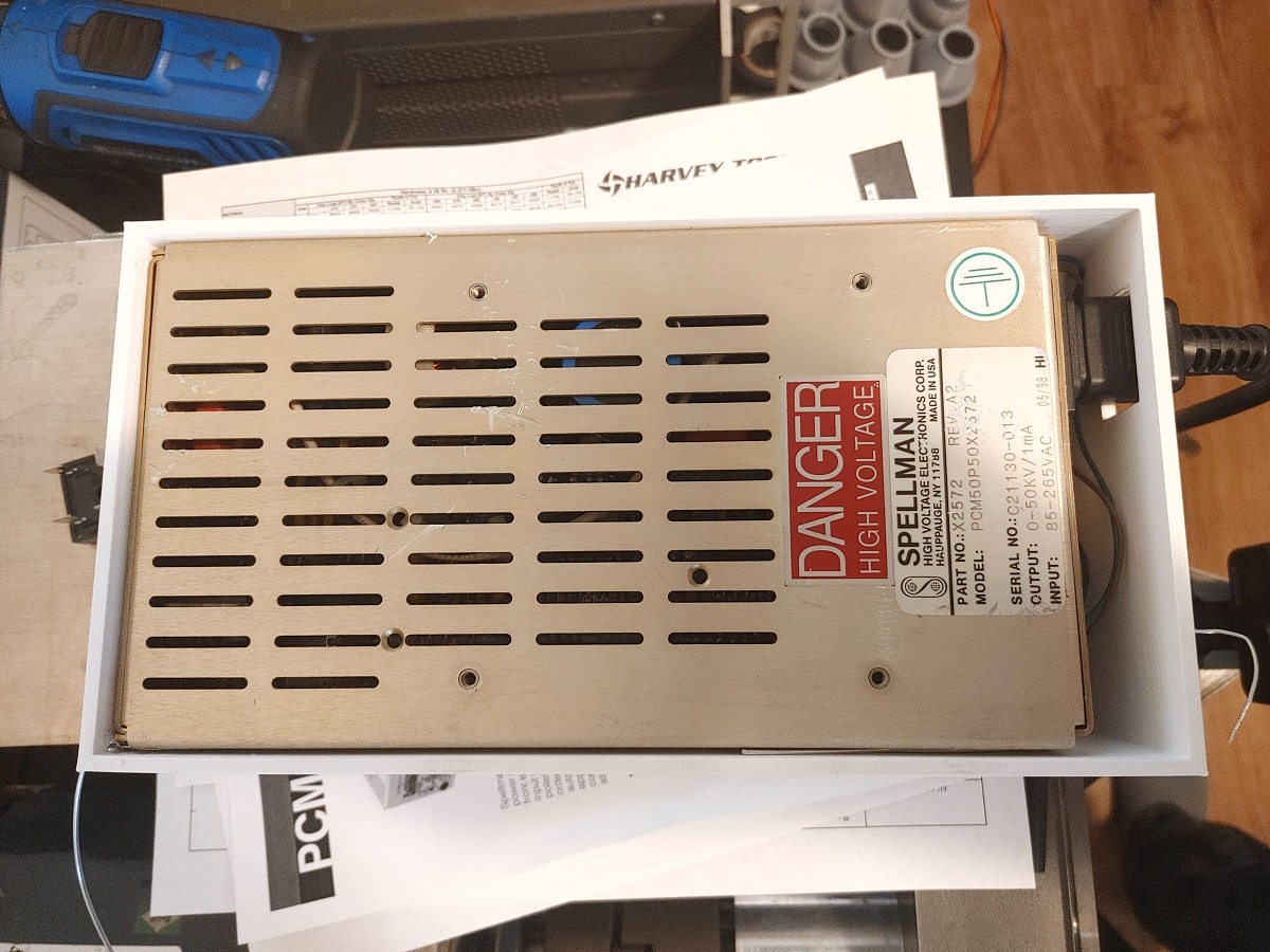
The power supply fits in the case.
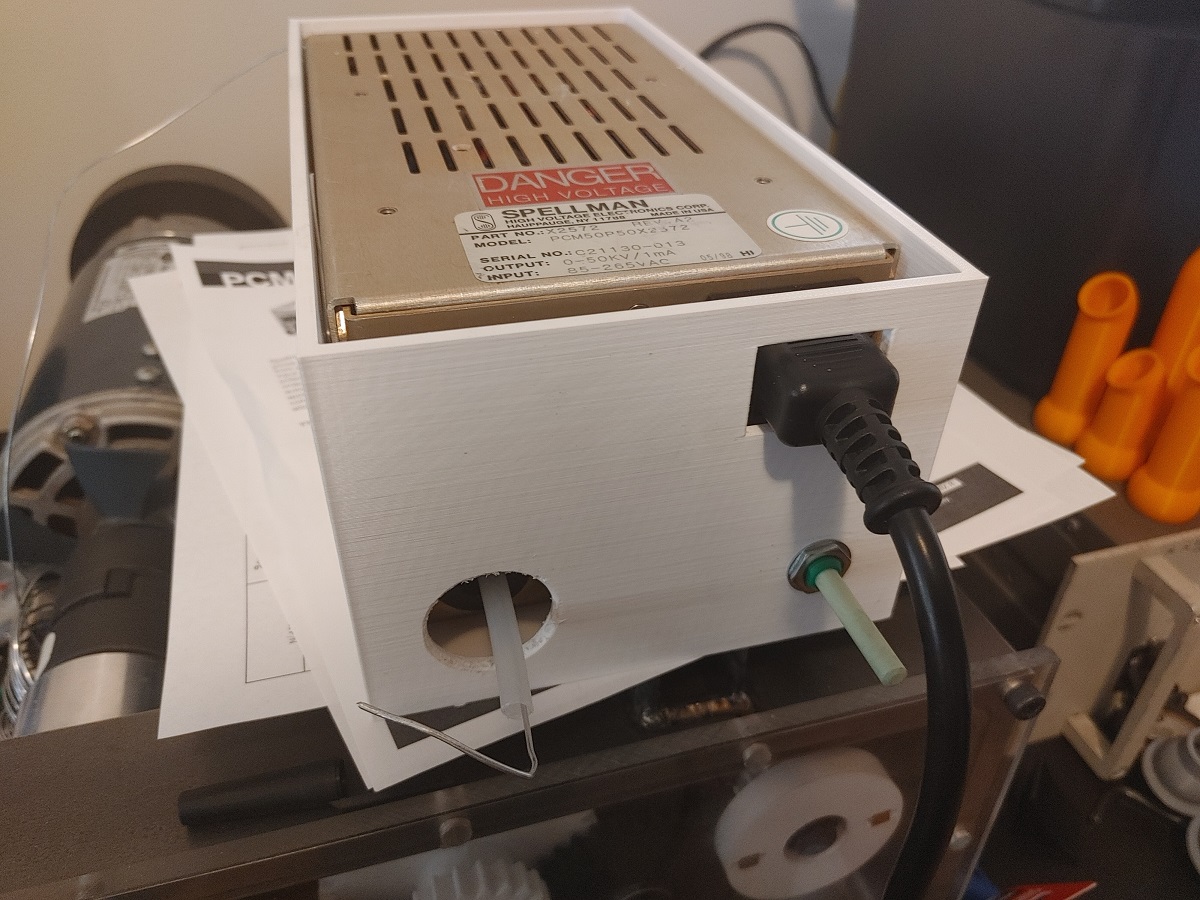
The potentiometer acts like a stop so the supply won't move around, the bottom cover is glued on.
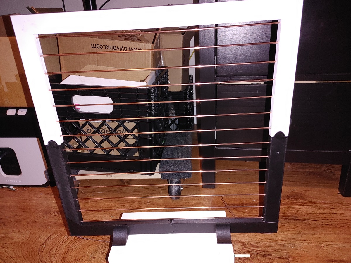
Here is the whole thing glued together along with the wedges for supports. The grids are glued and wired in place.
Here is a quick test video of it working. There are a few issues with insulation, those I have to sort out before part 2.
The project is not quite finished until I sort out the insulation issues and kill some flies.
Hello, if you have enjoyed reading this project, have taken an interest in another or want me to progress one further then please consider donating or even sponsoring a small amount every month, for more information on why you may like to help me out then follow the sponsor link to the left. Otherwise you can donate any amount with the link below, thank you!